


Motor design is key to the performance and service life of a pump. But people often struggle with determining the size of the motor required to drive the pump. This is especially true of wastewater submersible pumps.
 This article, written in July 2017 by Bo Gell, Americas product manager, wastewater, who has worked in Xylem’s Applied Water Systems business unit for six years. Gell has extensive experience in residential, commercial and marine pumps. Hayes Pump specializes in Goulds Water Technology products. Continue reading to continue learning from Bo.
It’s a common assumption that you can use motor nameplate information at face value. That applies to some, but not all nameplate data. A primary example is service factor (SF).
Generally, service factor is the measurement used to determine the peak performance at which a pump motor can operate. The National Electrical Manufacturers Association (NEMA) defines service factor simply as a multiplier that indicates the amount of additional load a motor can handle above its nameplate horsepower. The service factor industry standard for a totally enclosed motor is 1.0.
To determine the service factor horsepower of a motor, multiply the nameplate horsepower by the service factor. For example, if a 1 HP motor has a service factor of 1.5, the motor’s service factor maximum horsepower is:
(1 HP) x (1.5 SF) = 1.5 HP
However, when sizing submersible wastewater pump motors, horsepower service factor, which applies only to the motor, is not a primary consideration. While service factor can be used to handle intermittent or occasional overloads, designers cannot rely on the service factor capability to carry the load on a continuous basis. Doing so will likely result in reduced motor speed, and the reduced life and efficiency of the pump.
Designing Pump Systems for Continuous Duty
When sizing a submersible wastewater pump motor, it’s important to consider whether the pump will ever be required to operate at a flow rate higher than the design point. If, for example, the pump was allowed to operate at the end of the head capacity curve, the actual horsepower requirement may exceed the design point selected motor horsepower and overload the motor. For this reason, it is common practice to size the motor not for the design point, but for the end of the curve or maximum horsepower requirements.
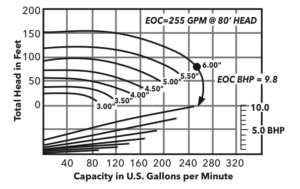
In the example above, a 7.5 HP motor would adequately power the pump at a design point of 120 GPM at 150 feet; however, looking at the end of the curve, brake horsepower requirements call for a 10 HP motor.
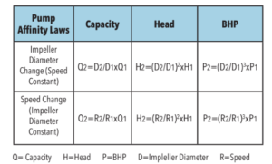
It’s also important to note that submersible wastewater pumps follow Affinity Laws – the mathematic relationships that allow for the estimation of changes in pump performance as a result of a change in one of the basic pump parameters. If either the speed or impeller diameter of a pump changes, you can approximate the resulting performance change using the following:
Pursuing peak pump performance
Taking all of these factors into account, the NOL Horsepower (or non-overloading brake horsepower) is a more accurate criterion when it comes to sizing the motor for a submersible pump. The NOL Horsepower is the maximum power value calculated in order to handle the maximum power demanded by the pump at any point along the curve. NOL Horsepower represents the amount of real horsepower going to the pump, not just the horsepower used by the motor.
Although not typically listed as part of the operational information on the pump nameplate, NOL Horsepower is one of the key factors confirmed during pump performance testing. If motors overload at any point on the published curves during testing, listing agencies like UL and CSA will not award product certification to the motor vendor.
While the factors used to size a motor that will operate anywhere on the pump curve may not be those typically used as defined for standard NEMA motors, there are advantages. Selecting a pump/motor combination that will function under all possible operating conditions will result in higher efficiency, longer service life and uninterrupted performance — even in a continuous duty application.